Luggage Rails

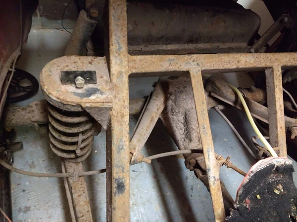
I had a pair of old aluminum luggage rails which were bought at an autojumble some time ago which I thought would be useful on the Madison as it has a very small boot space. I decided to mount them through, rather than on the fibreglass, so they could carry a decent weight if need be. Although I had a fair amount of metal structure underneath the tail section it took several mugs of tea and lots of thinking to work out a simple way of mounting them. I had a roof bar with brackets from a VW Passat which I was able to adapt; I cut two short lengths of the bar and removed the feet from the brackets such that I was able to bolt the brackets onto the roll bar cross brace (following Colin Chapman’s maxim that every fitting has at least two jobs if possible).
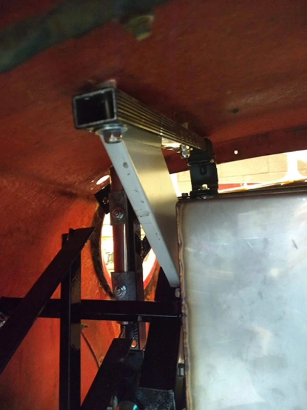
I also had a length of metal sheet which was like a large U shape with folded ends that had two captive nuts in each end – it’s the grey metal piece you can see above. This came out of my ex British Gas VW Caddy which had a complete racking and storage system inside it when I bought it. One end of the U section rests on the angled rear roll bar brace and is bolted through it using the captive nuts – the other end was cut at an angle and then pop riveted to the side of the shortened roof bar. I hope that’s a good enough description!

I then drilled holes in the fibreglass tail and cut short lengths of thick aluminum tube which rest on the support bars underneath. These lift the luggage rails above the body and are necessary so that a flat item such as a suitcase will clear the centre of the tail which has a raised rib in the middle.
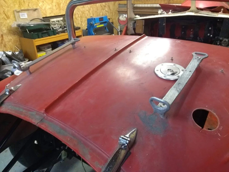
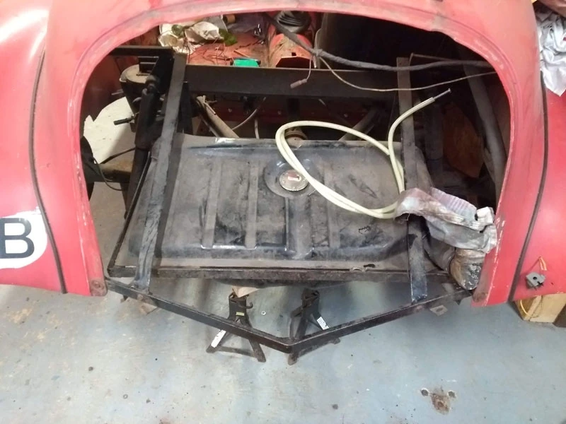
The photo above shows them bolted on, they need further cleaning but I’ll be keeping some of the “patina” on them. You can also see the new flush petrol filler – I was going to have a more traditional filler cap but it would have fouled on the luggage rails. If I’d thought further ahead I could have had the tank filler further over when I had the tank made but it’s a small compromise. You can also see the old petrol filler hole, this will need filling in etc at some point soon…
Finishing off the back end

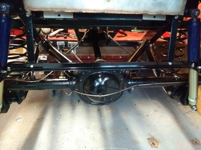
Having got all the parts back from the powder coaters the next job was to assemble the rear axle with the brake backplates and to then bolt in the halfshafts with their new bearings. New brake cylinders were fitted and after a bit of puzzling via the Haynes manual and YouTube the mechanical adjusters, handbrake cable ends and mechanism were assembled (it’s been a while since I stripped it down and I’d forgotten how it should go). After this I made up some new brake pipes and put the axle back in the car.

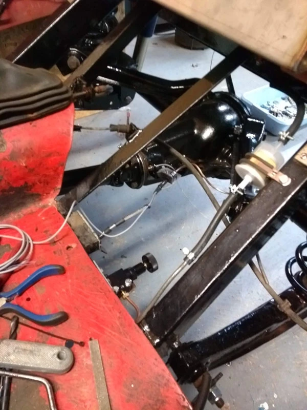
I bought a set of Goodridge braided brake hoses from Burton Power which were specced for the Cortina donor and the rear hose turned out to be much shorter than the one that was on the Madison. I went with it and added a small bracket to the propshaft speedo sensor pickup that I’d previously bolted to the axle. There is a short pipe to a 3 way union mounted where the flexible pipe would have originally gone. You can also see in the next photo the brake balance adjuster – I decided to fit one as the rear of the Madison is probably lighter than the donor Cortina (which is what the Master Cylinder is from) and it would be helpful to be able to balance front and rear braking. I bought this off eBay for £14.00 delivered from China. It looks identical to the Motamec Brake Proportioning Bias Valve which is nearly £50.. I accept that it might be a piece of crap but at that price I was curious to see what it was like. It arrived within a few days and looks and feels of good quality – time will tell of course. Other things to see in this photo are the primary fuel filter attached to the chassis rail via a large P clip and a bolt through a rivnut, it attaches to the existing metal fuel pipe via a short length of hose and is easily accessed from underneath when the car is in use – I rotated the hose clips so I could get a screwdriver on them etc..

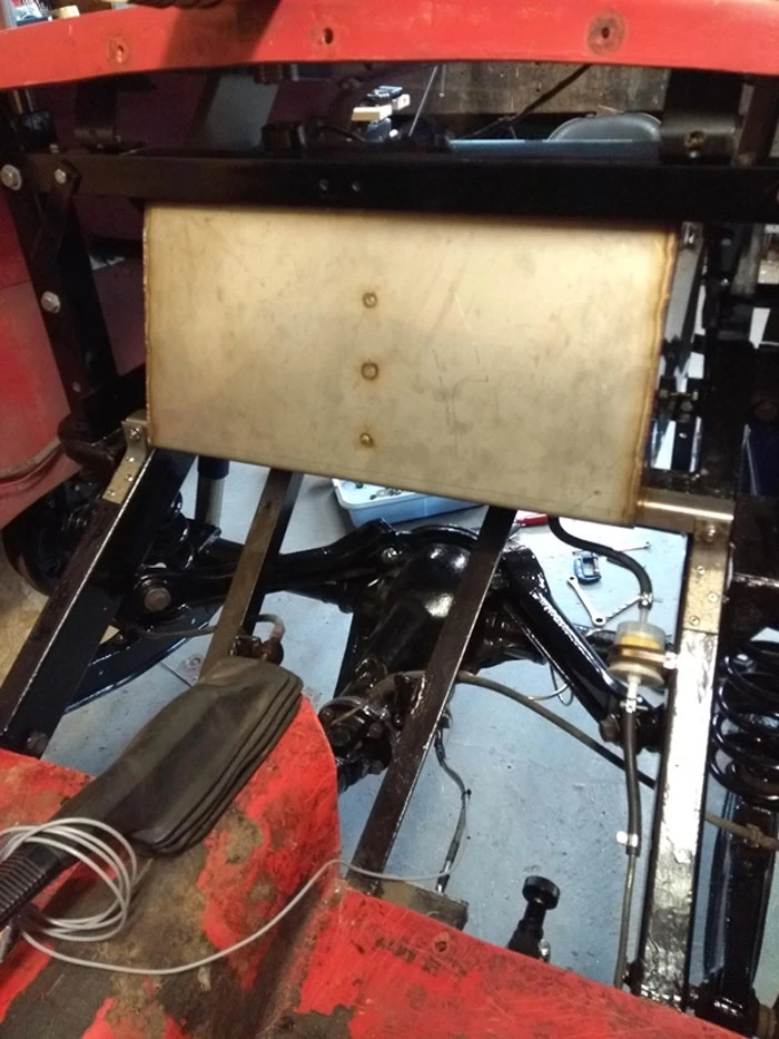
In the next photo you can see how the fuel tank sits nicely between the chassis rails and the handbrake lever installed with the old handbrake cables which rather let the “new look” down but they are perfectly serviceable so I felt I should use them. The cable wound round the handbrake lever is the speedo sensor pickup, I’ll run this along the tunnel inside the car and yes I’ve checked it will reach the speedo! The crossbar above the tank does several jobs – it braces the roll bar uprights, it provides a support for the rear bulkhead and now provides the front support for two luggage rack rails.

I never throw anything metal away unless it’s the size of a pinhead and had a roof bar from a VW Passat with the clamp fittings that had been in the recycle bin for years. I also had a pair of vintage looking aluminum luggage rails that I wanted to use as the Madison boot is tiny. I didn’t want to mount them straight onto the fiberglass so I cut the roof bar down into two short lengths and modified the brackets so they would bolt onto the cross bar – more pics next time I blog.

Several streams of work…

It seems a while since I last posted, a fair amount of work has taken place but not much to show until now…

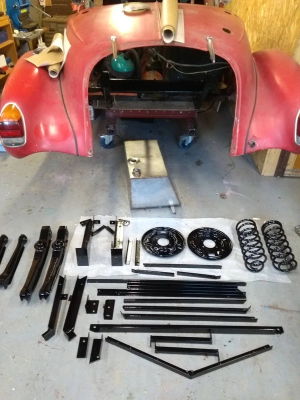
Having finished fabricating new supports for the tail section and creating a boot space I stripped it all down and together with most of the rear suspension bits paid the powder coaters a visit. I also asked Alan who runs Triking to make me a new fuel tank out of stainless steel. You can see the results in the next photo.

I used Colorcoat who are 6 miles south of Norwich, they did a great job and were very reasonable on price. This saved me a lot of time and effort and it’s a pleasure bolting shiny parts together with new nuts and bolts…!

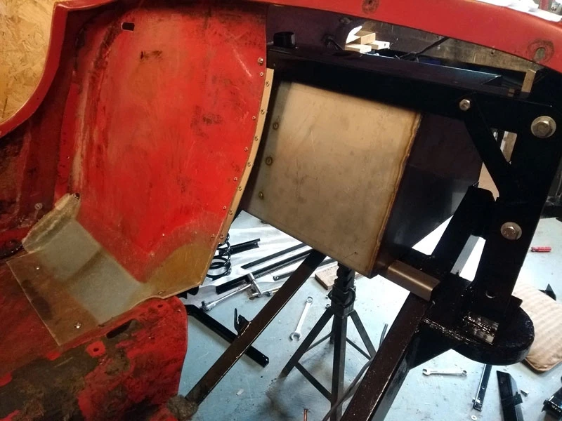
I assembled the roll bar supports into the car and then offered up the new fuel tank to finally position the brackets for it. Al made a really nice job of it, it has a central baffle as well as filler, fuel gauge sender, drain hole and outlet exactly where I want.

The photo above shows the fuel tank in it’s position above the rear axle and between the chassis rails, much safer than the old tank which was unprotected right at the rear of the Madison. You may also note that I’ve split the rear bulkhead into two, it was virtually impossible to get it in and out as a single unit, so now it’s much easier to offer each half in turn to work out where to put holes to allow the seat belt stalks through etc. The translucent parts are the new fibreglass pieces I added so I could move the bulkhead back. The tank is not fitted as yet, this was just to mark out where to drill the bracket holes, I thought it would be a good idea to fit the rear axle before the tank as I’d have a clear space to work in.

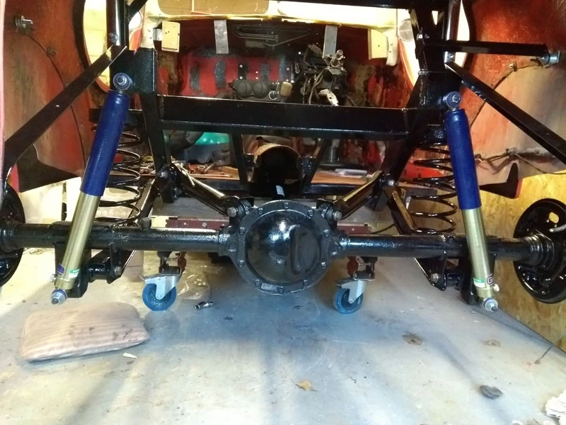
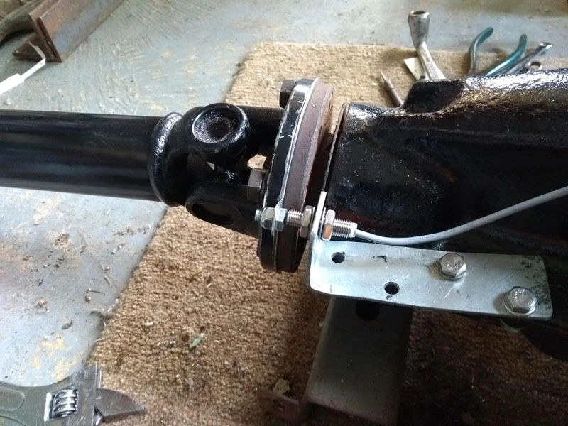
Here it is back in, with new adjustable Gaz dampers, new nyloc nuts all round and most bits powder coated apart from the axle itself. There’s also a new propshaft as the old one was in a mess with blobby welding and various pieces of metal pop rivetted on to balance it. The sliding spline collar was also very pitted and had ruined the gearbox tail oil seal. Getting the old seal out was fairly easy, fitting the new one was quite tricky at first with the gearbox in situ as it’s narrow and wouldn’t go in straight. I found a piece of plastic waste pipe that would fit over the splines and at the same time keep the oil seal aligned enough to be tapped into place. I’ve gone for a digital ETB speedo for the car so needed a pickup point for the sensor. I made a thin disc with a protuding tab that’s sandwiched between the propshaft and diff flange joint. I then drilled a couple of holes in the diff web to attach a bracket to hold the sensor as shown below.

Back to Work

There hasn’t been much work done on the Madison for the last few weeks as one of my sons bought a partially completed “Honda CG125 to Cafe Racer” motorbike that turned out to need quite a lot of work done – by me mostly – in order to get it MOT’ed and roadworthy.

Anyway, now that’s done, work can resume on the Madison. With the removal of the fuel tank there was basically nothing from the rear axle backwards chassis wise. The boot section of the body was only supported by the rest of the car body so needed some strengthening framework. I also wanted to attach the seat belt shoulder mounts to something more substantial than the fibreglass body. In addition I wanted to install a roll bar hoop to offer some occupant protection.

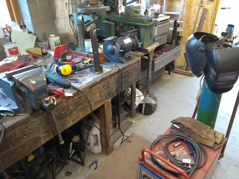
The rear section of the Madison chassis consists of two 4 x 2 steel box sections with substantial back axle coil spring support plates welded to them. Careful measuring showed that the uprights for a roll bar could be attached to them and that bracing bars from them could be attached to the end of the chassis rails. The uprights could also be used to mount the seat belt inertia reel and top mounts. I bought various sizes and lengths of angle iron from the local steel stockholder such as 50 x 50 x 5 for the upright bases and 50 x 50 x 4 for the uprights themselves and then 40 x 40 x 3 for various other jobs. Fortunately I have an old powered hacksaw that will slowly cut it’s way through the heavier gauge iron as well as a cheapish pillar drill. I’ve also got an old Britweld MIG welder that can be used on the heavy gauge iron if you go slowly and take your time to get the weld pool across both pieces to be joined. This picture shows my (scruffy) setup and one of the completed uprights.

I do actually clear my bench regularly and sweep up but generally seem to do most work on the area that you can see so it tends to have things I use semi regularly on the peripheries..

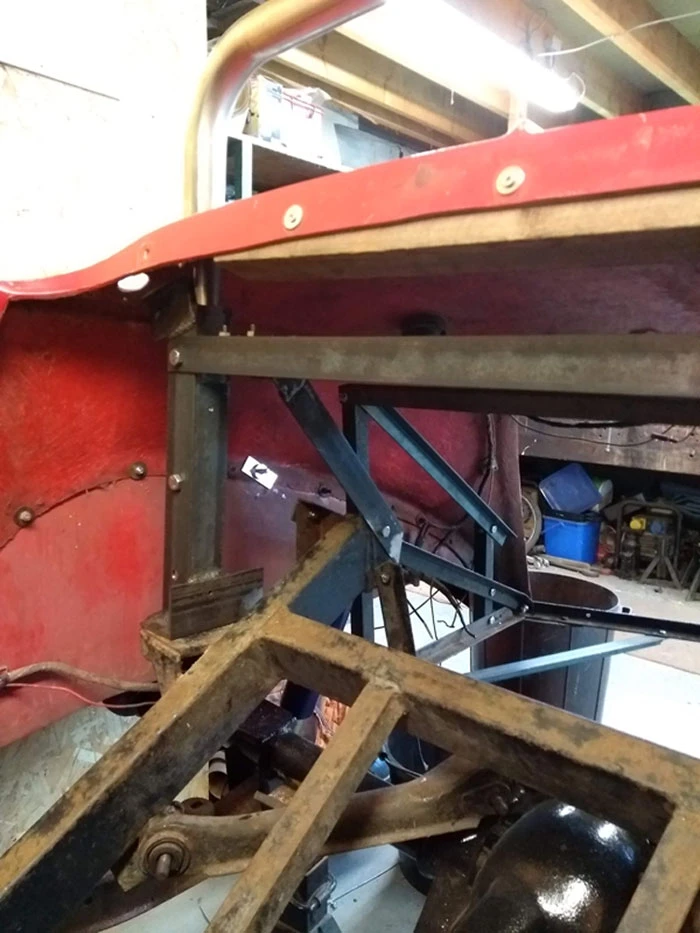
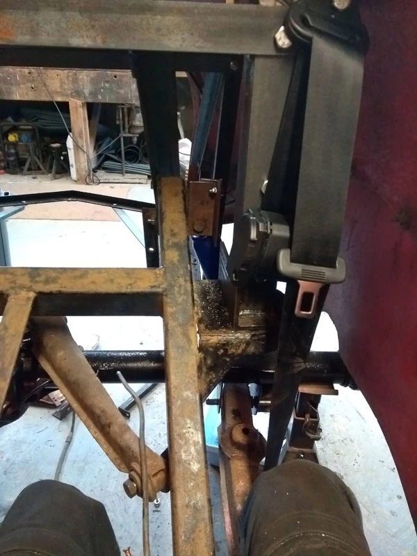
This next pic shows the uprights installed in the Madison. The base is bolted to the coil spring support plate with an M12 high tensile bolt. The upright is welded all the way round to the base and the roll bar is bolted to the upright. There is a cross bar attached to the top bolts and there is also a small plate on the side of each upright so the cross bar is bolted on both angles. Then there is a length of angle iron from the cross bar to the rear of the chassis rail each side. I will probably make a small triangular section each side where the uprights and cross brace join to increase lateral strength. The seat belt inertia reel bolts to the bottom of the upright and the top mount bolts to a welded on piece of angle that sticks out – easier to see in the photo above. You can also see in this photo the various pieces of small section angle used to support the rear of the body and make a boot space.

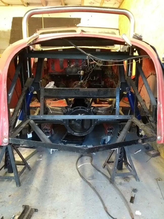
The photo below shows this all from the rear. The roll bar is stainless steel and was formed by my friend Al who owns Triking, it was tricky to get the slight curve in the top section but I thought it was important to follow the line of the body so it didn’t look too stark.

It’s probably worth saying that I realise the roll bar most likely doesn’t meet any official “standards” and that the same is true of the seat belts mounts etc. My own view is that what I’ve engineered is a lot better than what was there before with regard to the top seat belt mount in particular and that the roll bar will offer some protection as well as a grab handle when I get into extreme old age!

Finally, I’ll finish with this photo which shows how easy it is working on the Madison for certain jobs. I’m sitting in the cockpit facing backwards and you can see the seat belt test mounted to an upright, the two black things are my knees and my feet are on the ground…

Work on the blunt end…

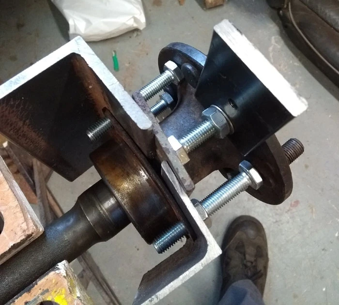
Following on from the last post I had to get the old halfshaft bearings off without damaging the halfshafts so I made up a tool out of angle iron and six M10 bolts which removed the bearings very successfully.

Homemade Extractor

New bearings and retaining collars were quite cheap at approx £20 per side so these await being fitted via a friends press.

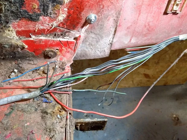
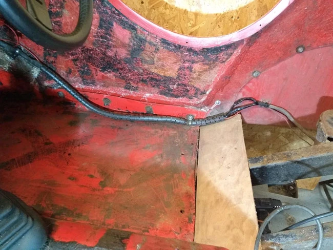
With work shifted to the back of the Madison several parallel jobs needed to be done such as; calculating dimensions for the fuel tank, working out how to attach a roll bar and seat belt mounts and moving the rear bulkhead back to make more room in the cockpit. The existing bulkhead had been removed somewhat crudely and the saw had left its mark. I started to tidy up the wiring loom where it passes through the cockpit and discovered part of it had been cut through in two places so I had to mend it using several different methods.

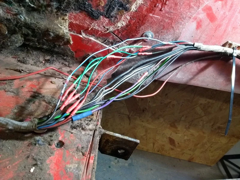
A number of wires had missing sections so for those with bright ends I added new pieces soldered in, wrapped in tape and then heat shrink sleeving. One of the wires had that blackness that won’t take solder so I used one of the heat shrink connectors that CBS supply. These have a solder ring in the middle and then a glue ring each end. Although the old wire won’t take solder the new one would and once heat is supplied a slimline join results that is sealed against weathering.

With the loom fixed I rewrapped it with loom tape then put a strong nylon sleeve over it.

I’m not sure if the rear bulkhead was a separate one piece fibreglass moulding or part of the floor pan as there was evidence of sawing on it and the floor pan. Anyway it was evident it would need a lot of work as it didn’t fit the body with a 10mm gap one side. I also wanted to move it back a bit so after some head scratching I tidied it up by cutting a bit more off the edges to get straight lines and even curves. I then cut it in half such that it fitted snugly on the curved body sections and bolted a thin piece of ply to fill in the gap. I then made a curved aluminium piece to extend the transmission tunnel back and additional pieces of ply to fill in all the gaps. Finally I used plasticine to smooth out all the corners etc prior to fibreglassing. The next job was to apply new fibreglass over these sections and also redo the body joins.

The body on the Madison was made in three sections; a floor pan, the body tub and the wings/running boards. These are bolted together all along the body and in the cockpit some fibreglass mat had been applied over the join but quite honestly I don’t know why they’d bothered. The more I work on the Madison the more I appreciate what a quality moulding it is with fine detailing and a top quality layup. By way of contrast the fibreglass over the join was very poor; the surface hadn’t been rubbed down, the mat hadn’t been wetted out etc so I was able to pull it off quite easily by hand. As part of the bulkhead work I’ll redo these sections as the previous poor work had resulted in water getting through and the bolt heads rusting away.

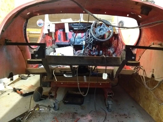
Pictures of the bulkhead next time but for now here’s a shot looking through the boot opening – lots of space at present !

Swapping Ends

Most of the work on the front end apart from headlamp wiring and bodywork has now been done, so I decided to switch my attention to the rear. After clearing some garage floor space I was able to pull the Madison forward and spin it around in the garage on the trolley, then tuck it into a corner again. This still gives me access to the dashboard area which is currently being varnished multiple times in order to try and build a decent finish on the burr walnut – more on that another time.

With the rear bulkhead removed – it’s just bolted in – and the boot lid removed access is very good at the rear of the Madison.

Rear axle and suspension.

Those of you familiar with the Cortina Mk3/4/5 range will have spotted that it’s a complete Cortina rear end, this is the Atlas axle with a 3.75:1 Diff which is the one to have apparently. The first job was to remove the fuel tank and in my case dispose of it as I don’t like where it is situated at the very rear of the car with zero protection from a shunt. My plan is to have a new stainless steel tank situated high up between the rear chassis rails, I can get one made to fit comfortably with a capacity of 44 litres which should be adequate for most journeys. I’m also going to fabricate a substantial steel frame bolted or welded to the main chassis situated behind the rear bulkhead for seat belt mounts and roll bar mounts. This will protect the new fuel tank still further.

Existing vulnerable fuel tank

The other thing about having the fuel tank moved is that I should get some reasonable boot space as currently there is none!

So it was now onto removing the rear axle. Fortunately the person who built the car had greased the bolts – or maybe the oil mist off the leaking gearbox rear oil had helped too. Anyway, with the exception of the propshaft bolts it all came apart fairly easily though it helped that I’d bought one of those very long 1/2″ drive socket bars as the nuts were really tight. I couldn’t get to the propshaft bolts easily so removed the axle complete with propshaft out the back of the Madison. I’d forgotten how heavy rear axles are, it’s quite a weight just dragging it over the floor. I unbolted the propshaft which looks like it could be for the scrap bin. The front splined section surface is badly pitted so it’s going to rip out a new oil fairly soon although I could possible have it skimmed or resurfaced. The main problem is that the shaft itself has been badly shortened with lumpy welding at the tube ends and various bits of metal pop rivetted on presumably to try and balance it. Looking around, new ones can be bought for approx £250 which is the easiest solution, not that I want to throw money at the car..

Stripping down the back axle

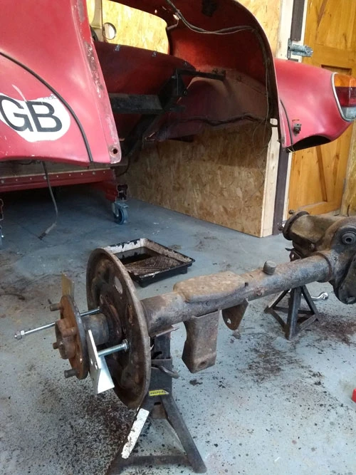
With the back axle completely removed I started to strip it down as I want to paint it and have the suspension arms powder coated as well as the brake backplates. It looked like the nearside halfshaft seal was leaking once the brake drum was removed so that made it necessary to remove the halfshafts anyway. The Heynes manual was very helpful on how to do this and in the picture above you can see how it’s done. The hub has two holes so you use two long bolts with metal plates such that when they’re tightened it pushes the hub out from the axle.

With both halfshafts out the backplates could be put with the other suspension components ready for the powder coaters. The axle itself is too heavy to take and I don’t want to strip it down anymore so a good wire bush and sand and it could be painted with smooth black hammerite.

Progress but not much to show…

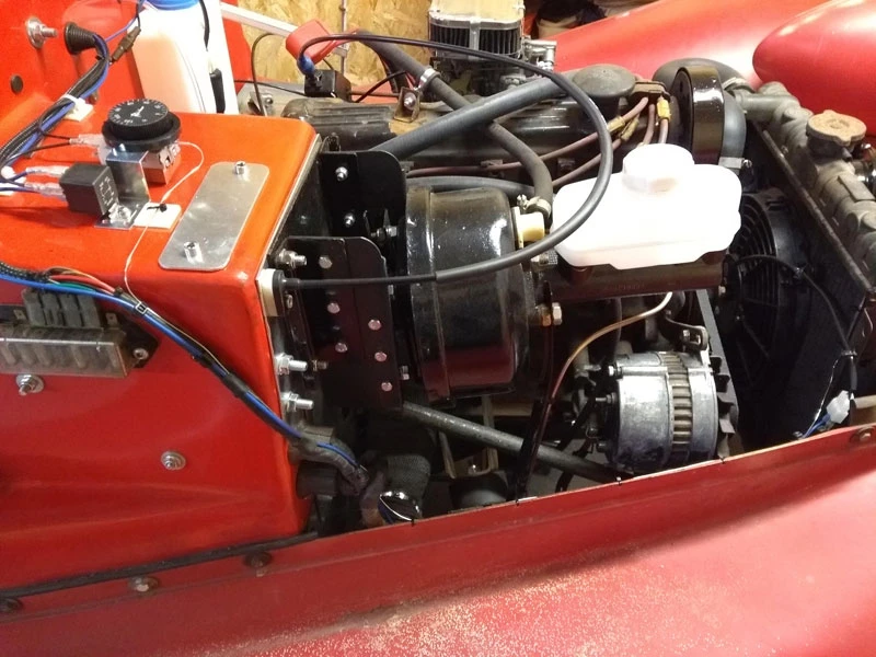
Work has continued on a regular basis with the Madison but with lots of small jobs that don’t make such a splash! I made up a battery tray and relocated the coil to a better position. I replaced the engine mounts and all the hoses, dropping the radiator by 30mm so the bottom hose didn’t rub on the steering shaft. I fitted an electric cooling fan with a thermostatic switch, new clutch and accelerator cables, tidied up more wiring and made sure the earth returns were clean and sound. I think I’m going to have the cam cover powder coated and make up a support bracket on it for the hose that crosses over the top. I’ve also relocated some of the wiring loom and rewrapped it in the interests of tidiness and avoiding chafe and/or strain points.

I then decided I should tackle the exhaust system and originally thought I would have to replace the whole system, judging by the state of the lower manifold coupling. However, it soon became apparent that if I did I would need a bespoke exhaust manifold with a hefty price tag, as nothing Pinto based that would fit the space was available off the shelf. I therefore looked again at the exhaust manifold which had been wrapped. Once that was removed and the rust tapped off it, the top half of the manifold proved to be very sound and solid so I cleaned it up and wrapped it in exhaust tape and it looks very presentable.

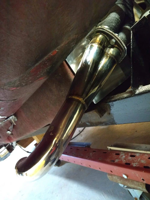
The manifold goes from four pipes to two pipes and then has a flanged join. The lower part where it goes from two into one had a stainless pipe welded on with so much weld that it was impossible to get the three 8mm bolts in it, instead weedy 4mm bolts had been used (and a mole grip on one side). I disc cut the pipes off close to the flange and then phoned up my friend Al, who owns Triking Sports Cars, to see if he could help. The Triking is a 3 wheeler car very much in the style of the 3 wheeler Morgan but with a Moto Guzzi V twin engine and gearbox and it is beautifully engineered. Al is incredibly helpful with a well equipped machine shop so I took the flange over to him and he made me a two into one section with a right angle bend. The picture below shows the before and after and it is the same metal flange believe it or not..

Before and after exhaust flange

This is it installed in the car, the Madison has a side exhaust under the running board so it’s nicely positioned once I work out how to support the heavy silencer…

Instrument Panel

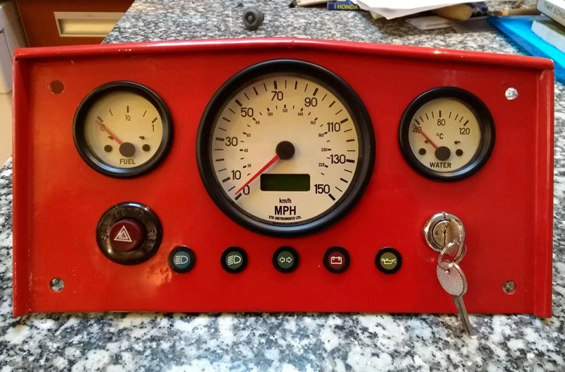
In previous posts you’ve seen a glimpse of the new instrument panel I made out of sheet steel. I decided to keep it simple and go for a large central Speedo with a temperature gauge one side and a fuel gauge the other, as the minimum essential instrumentation. Oil pressure and alternator charging will be taken care of with warning lights which I’m more likely to notice (or hear!) A Tacho would be nice but as this is a cruising car I’m not likely to want max performance in each gear and I could always add one later. The instruments came from ETB instruments who can provide a range of styles to match your car, they’re expensive but very good quality. The speedo is digital so can be programmed to the car and I’ll be using a propshaft sensor. The warning lights came from CBS, very nice black aluminium with LED lights but again not cheap. All in all this complete panel has cost around £400 with sender units but it is a focal point inside the car.

Completed Instrument Panel

I used a holesaw for the two smaller gauges and a jig saw with a metal blade to cut out for the speedo – very slowly I might add. The holes were then cleaned up with a file. The hazard switch was a pain as the cutout is a very odd shape – lots of small drilling and filing to get a snug fit. The paint finish is several coats of Smooth Hammerite, baked on top of the garage storage heater for a few days and then sanded with 800 grade wet and dry. Finally it was polished to a dull sheen with T Cut, it has some very minor blemishes to give it some patina, cheating I know but it’s my car… 🙂

A little bit of heat…

The Madison had no heater and I’d been debating whether to put one in or not. My Triking is powered by a Moto Guzzi engine which being air cooled provides no heating potential so I’ve often had “character building” drives in the British summer weather. I’m planning to use the Madison all year round and have a tonneau cover with a zip in the middle to close off half the cockpit, so it seemed worth putting a heater in before the dashboard went in as it would make access more difficult.

I find the website at Car Builder Solutions a good source of parts and they have several heaters available, including a small self contained unit that only needs power and a hot water supply. I decided to go for this as it would easily fit.

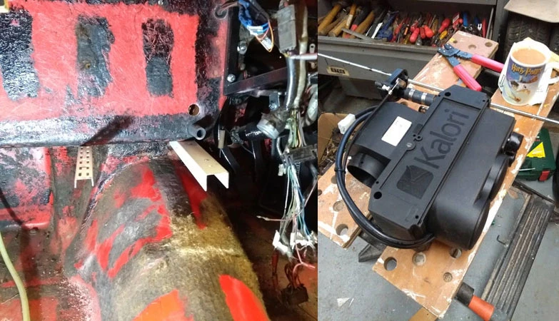
Before fitting the heater it was time for an unpleasant job, namely removing the old carpet and sound proofing which was filthy and crumbing to bits in places releasing fibres and dust, a grim job but such is the lot of us car restorers..

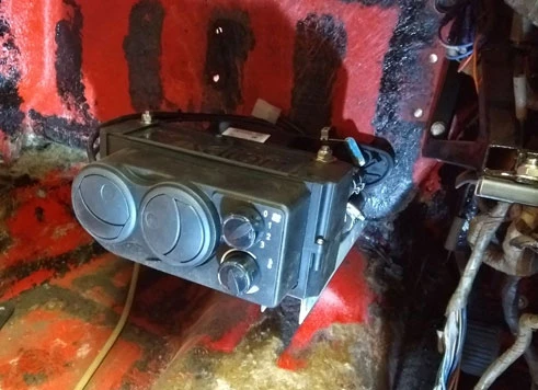
Once cleaned up I used a couple of pieces of old metal shelf brackets bolted through the bottom of the bulkhead panel to install the heater on. You can see how compact the heater is – the mug of tea is so you get an idea of size!

With the heater positioned onto the brackets I could mark where the heater hoses needed to go through the bulkhead and drilled them with a hole saw. The heater was then bolted to the brackets using a couple of pieces of threaded rod and looks quite neat I think. It gives out just over 4KW so should warm the car up with a half open tonneau cover, failing that maybe I’ll go for a Kayak spraydeck!

The Dashboard Challenge

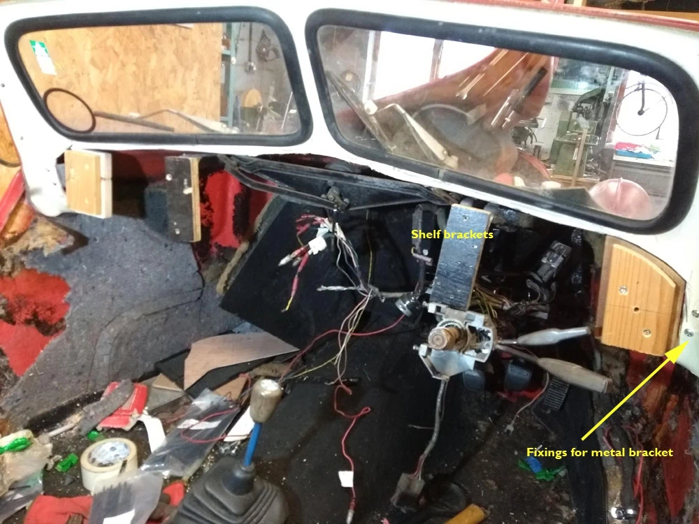
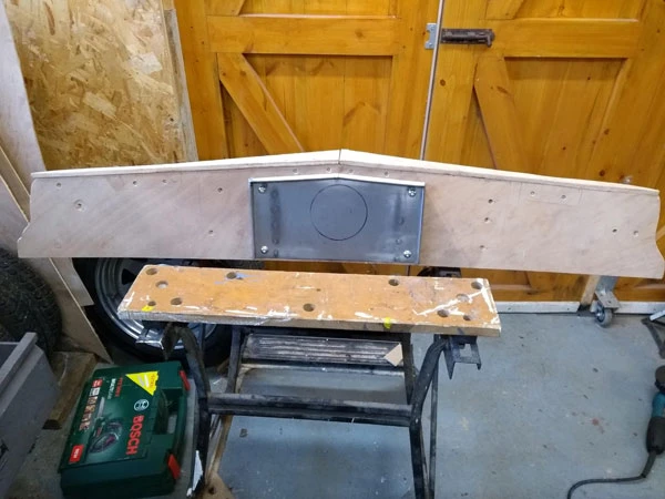
We’ll have all heard the phrase “blank canvas”, well this felt more like a cut up and ripped canvas when I first looked at it. There was virtually nothing to fix a new dashboard too as the original fibreglass moulded dash had been removed and cut back/broken off very close to the windscreens. At the cockpit sides there was a small amount of very thick fibreglass where several mouldings meet so eventually, after a lot of head scratching and measuring I was able to get a couple of fixings using some galvanised metal brackets from Wickes.

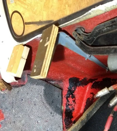
I drilled through the fibreglass and managed to get a couple of long bolts through to bolt the brackets on. The brackets themselves were “formed” (a term we used in IBM to describe metal bashing) such that they curved round the fibreglass bits and presented a straight surface to which bits of wood were screwed too. For the middle supports I had a rummage in the “it will come in handy one day bin” and found a couple of very long shelf brackets. These were long enough such that I could bolt them to the cowl or scuttle and they’d be hidden when the bonnet was shut. This next picture shows the view from underneath.

With these brackets in place I had something to build a dashboard on. I did this by using multiple sheets of 4mm ply glued together to get some curve and shape to the dashboard. Once dry I then made some pieces to fill in the gap between the windscreen and the dash and glued them on.

Now, I have to confess I love a well equipped dashboard; Speedo, Rev Counter and a cluster of Smiths short scale gauges (showing my age here) set off in a burr walnut dashboard does it for me. I will be veneering this with burr walnut but wondered what I should make it look like. I looked on the web at dashboards from cars in the 30’s and 40’s and they’re generally fairly simple and made of metal. A metal dashboard is much easier from some aspects, particularly when mounting switches and warning lights, as some of them only have a few mm of thread. A further consideration was that the donor Cortina has lots of column mounted switches so I didn’t need to have that many dashboard switches. I don’t want to pretend that this is an old car but I did want to keep to the style otherwise what would be the point of the project. So, I decided to go for a simple metal dashboard which will have a big central Speedo and fuel gauge and temperature gauge either side. Warning lights will cover oil pressure, alternator charging etc and there will be a couple of switches including ignition and a starter button and of course choke.

The metal part of the dashboard is a piece of 1mm sheet steel cut and folded in one of those Clarke guillotine/folding/rolling machines that Machine Mart sell – an early lockdown treat. Where the folded edges meet I’ve MIG welded it and filed it smooth. It actually makes the wiring/dashboard build much easier as it can easily be removed whilst leaving the main dashboard in place. This really needs to be bonded to the remains of the old moulding at the bottom of the windscreens, so once it’s in I don’t want to have to take it out again.

https://diamond-profit.co.za/ | anabolicstoreja.net | true fortune casino | Tweedbet | Betking | Topmatch | Spindog casino review | TenoBet Casino | Foxy Gold Casino | 12 pots of gold drums | andriol | official site